Lithium Iron Phosphate (LiFePO4) Battery and BMS Build
by Sidney Kantor
The electric buggy that I built was originally powered by two 12V lead-acid batteries in series and I was never satisfied with that setup so I began searching for some LiFePO4 cells to build a battery. I found 25 AH cells that were the perfect size for what I needed. The cells were rated at 3.2V with a 75 AH discharge rate. The cells were apparently leftover cells from an electric vehicle manufacturer over seas.
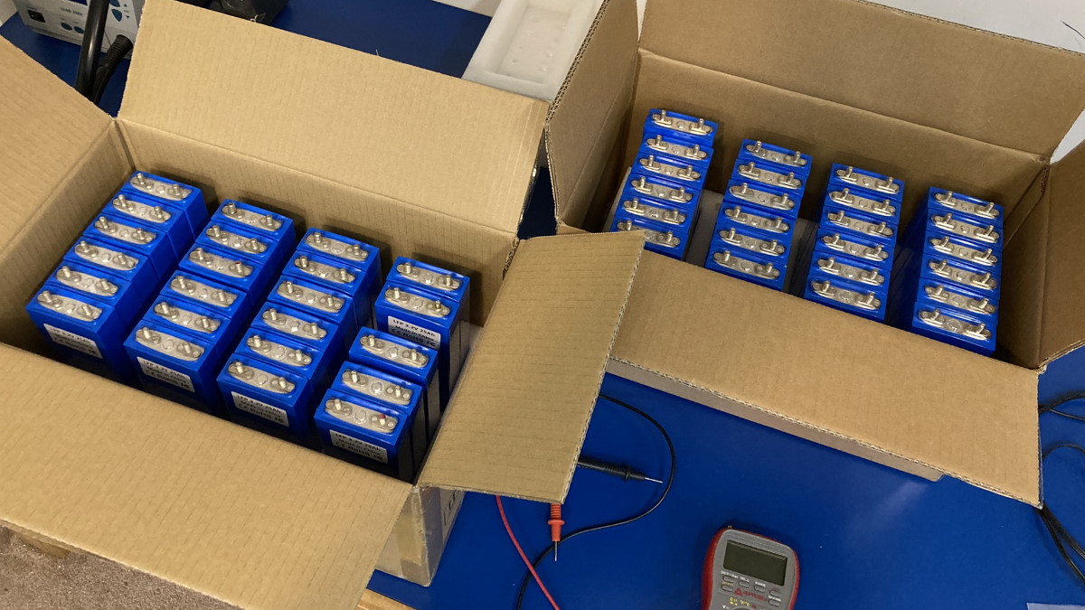
Unpacking the batteries.
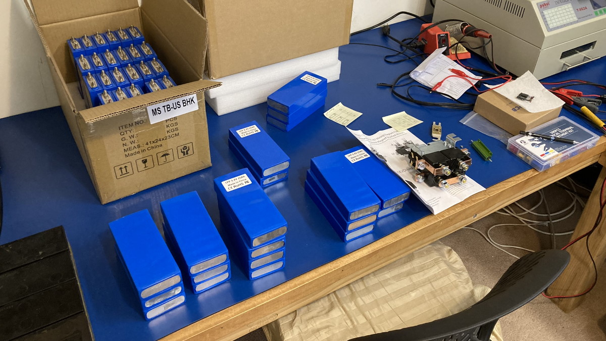
Unpacking the batteries.
I needed to experiment a bit and fully vet the cells. I started with a few cells and checked their voltages and then proceeded to charge four of the cells, first in series, and then in parallel. The cells charged without an issue, however, as was expected, I was going to need a BMS to ensure the cells remain balanced during charging and also to prevent over charging of any of the cells.
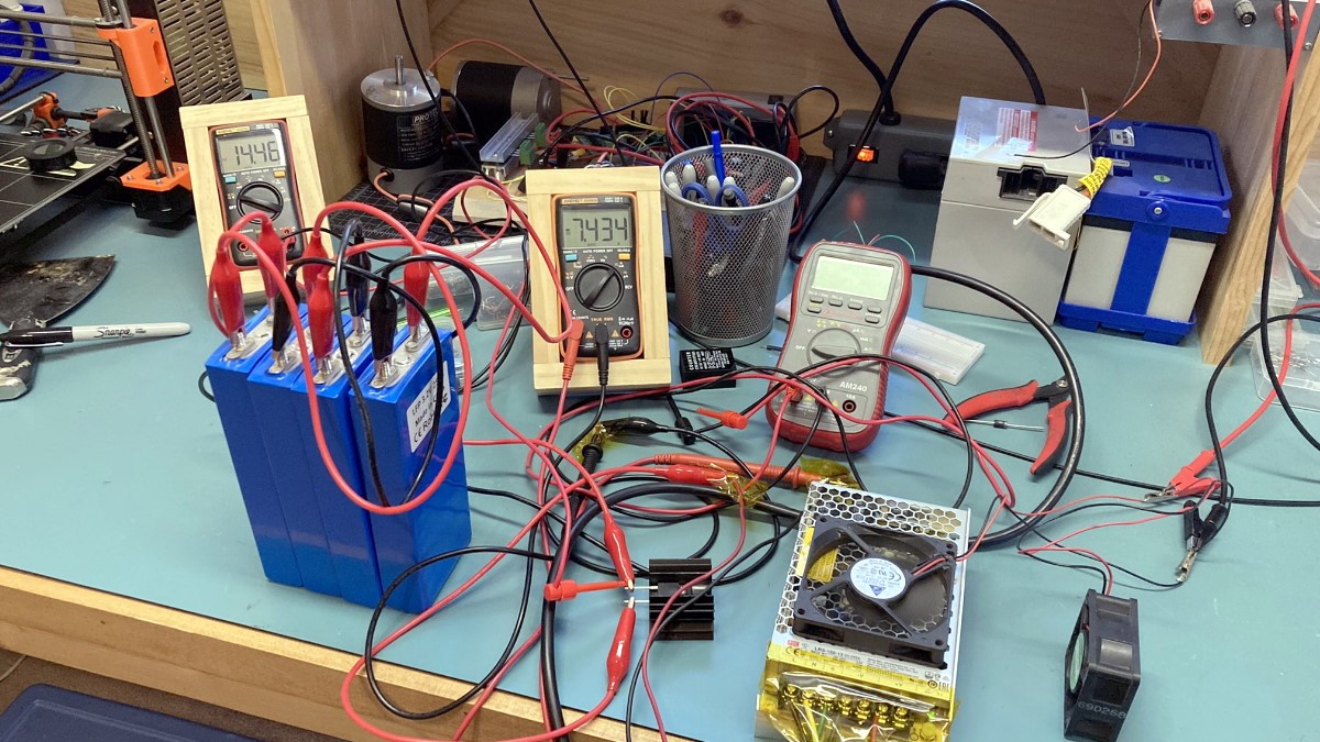
Initial charging of a few of the cells.
I decided to use a 3P16S configuration. This configuration puts 3 cells in parallel and then 16 of those blocks in series. This gives a nominal voltage of 51.2V and a capacity of 75 AH with a safe continuous discharge rate of 225 A. I used copper bus bars that I made from copper stock.
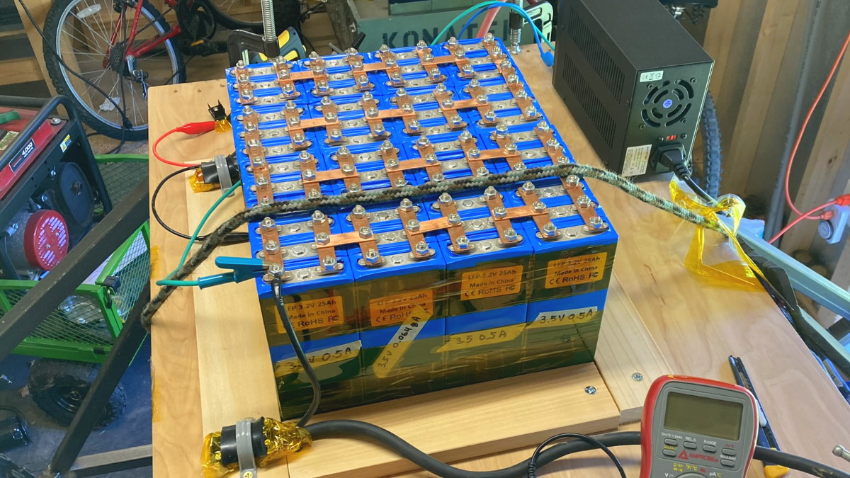
The assembled battery getting ready for initial testing in the electric buggy.
The problem with simply charging LiFePO4 cells in series is when they are not balanced, i.e., the cells are not at the same charge level or voltage level. If you were to charge four of the cells in series at 14.4V, then in theory if the cells were perfectly balanced and matched, each cell would drop 3.6V until fully charged and until the current dropped significantly to a trickle charge. However, in practice that is never the case. The same current is flowing through all of the cells. As soon as the first cell reaches a fully charged voltage of 3.6V you would have to stop charging which would prevent the charged cell from being overcharged but then the remaining cells would be undercharged. If you let it continue charging then that first cell would be overcharged and it could not only damage the cell but can be dangerous.
One of the things a battery management system (BMS) does is to manage the charging of the cells to ensure that each cell gets fully charged but not overcharged. A quick design I did (see schematic below) addresses the issue. The design is not without issue, however I will describe how it works. I used a capacitor with some series resistance to act like an analog for each cell. The cells are connected in series and each cell is in parallel with a BJT. A differential op-amp monitors the voltage across each cell. As soon as the voltage across a cell reaches 3.6V it drives another op-amp that then drives the base of the BJT turning it on an allowing the current to bypass the cell. This allows the charge voltage of any fully charged cell to remain at 3.6V while allowing the current to continue charging the other cells. This continues until all the cells are charged. If the cells are only slightly unbalanced then this design works well. However, the larger the imbalance, the more current that the BJTs have to bypass and therefore, the more power they have to dissipate. There are lots of other more sophisticated designs that solve the problems I mentioned but I just wanted to talk about this initial design as a nice starting point for the design of a BMS.
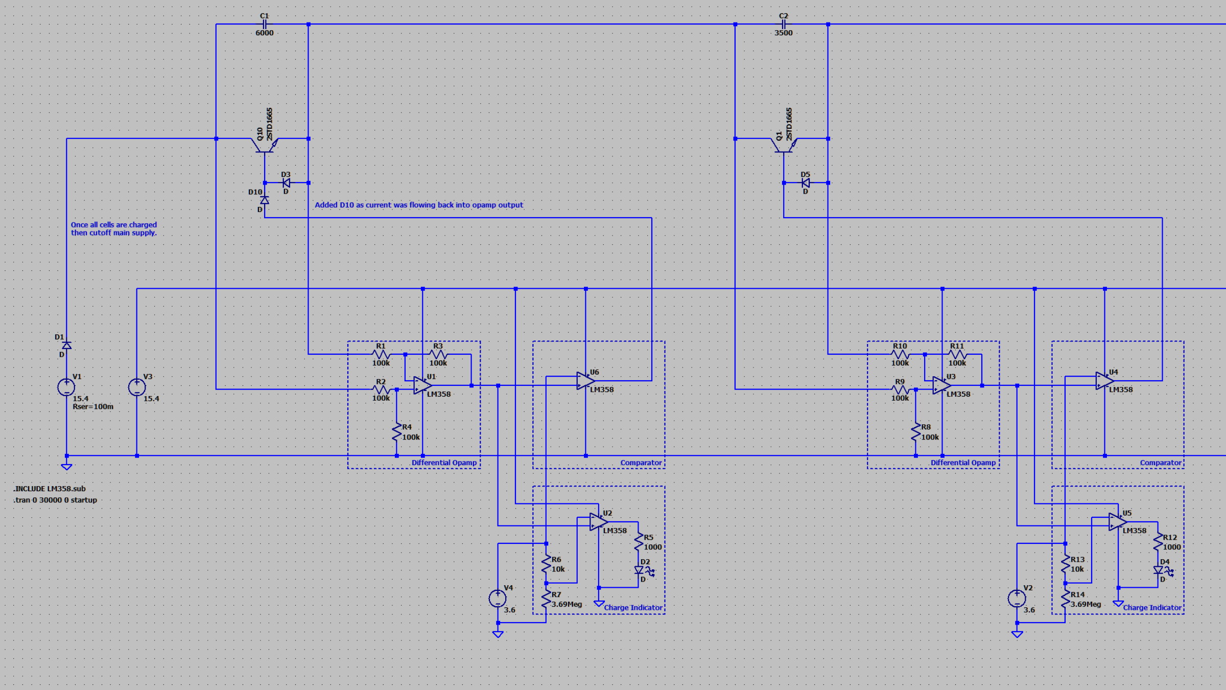
Initial rough schematic of a BMS circuit for the charging of four cells in series with over voltage protection.