PIC Development Board
by Sidney Kantor
Schematic
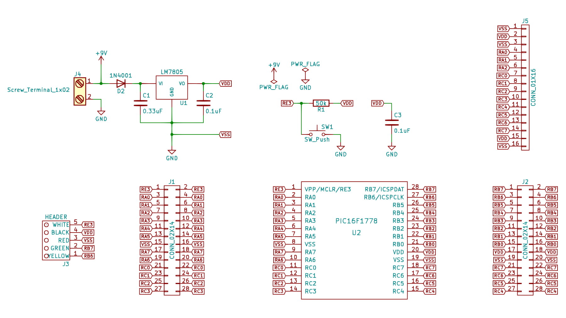
My entry into microcontrollers was with the PIC series of microcontrollers from Microchip. I was using the PIC16F1778 microcontroller in a lot of my projects so I decided to design a development board for it. The board has breakout headers for all of the microcontroller's pins, a terminal block for connection to power, a hard reset button and a 16 pin breakout header for an LCD. It also has a 5 volt regulator, a diode for reverse polarity protection and a 5-pin programming header.

PIC Development Board schematic done in Kicad.
PCB Layout
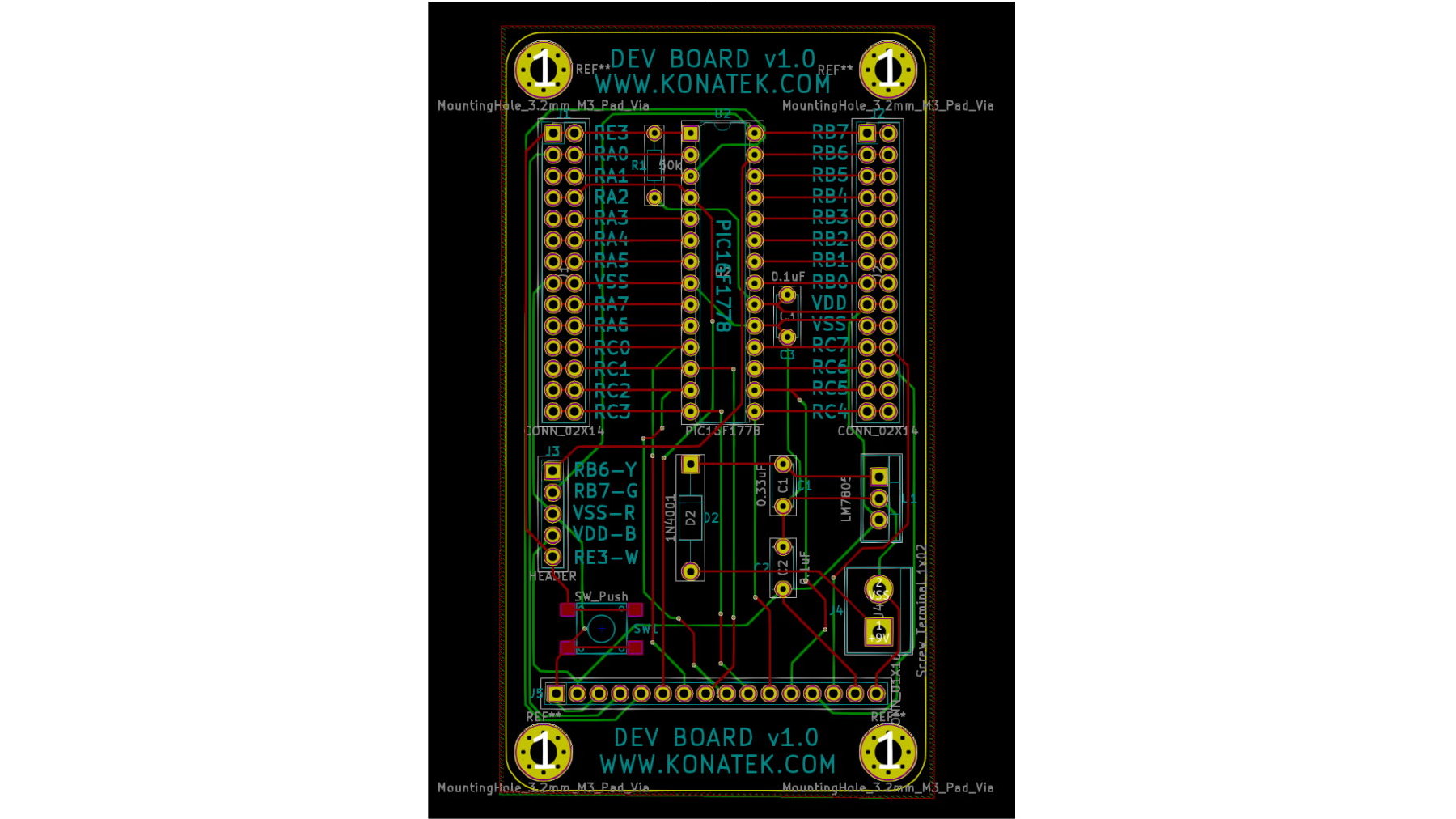
I'm a big Kicad fan so that is my schematic capture & PCB design software of choice. Below is the PCB layout of the development board.

PIC Development Board PCB layout in Kicad.
3D View
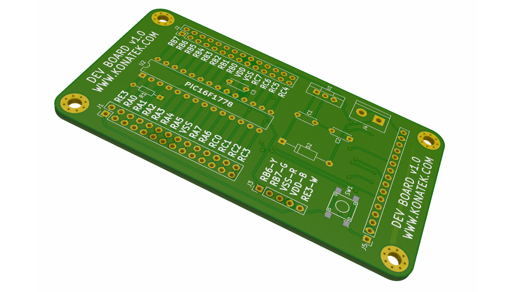
Kicad has a really nice and built-in photorealistic renderer. Below is the rendered development board.

PIC Development Board rendered in Kicad.
Final Board
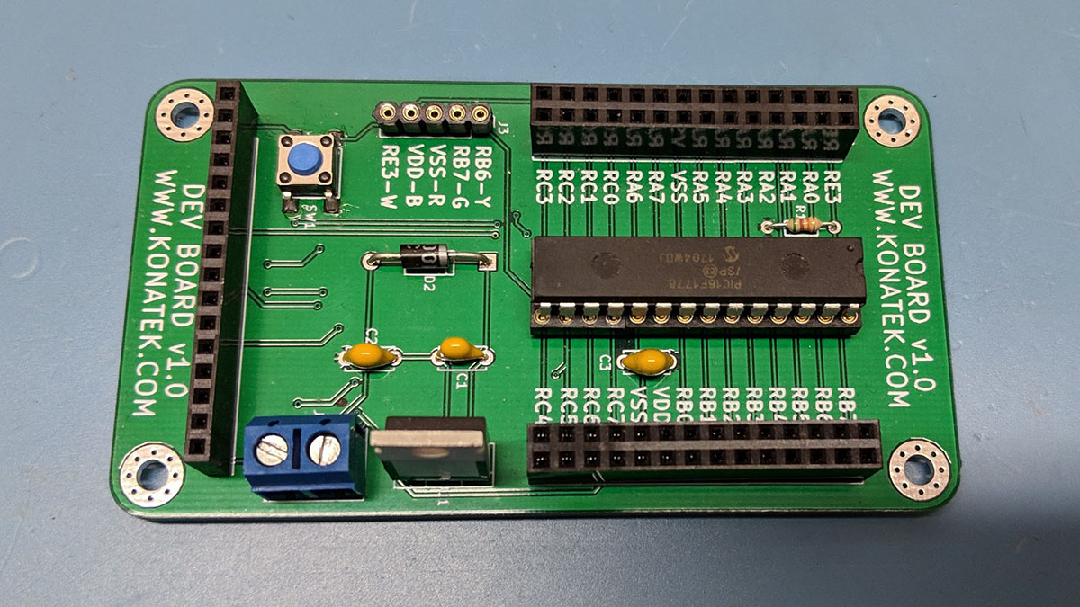
The final development board after manufacture and population of components. I think I ordered 20 or so of these so they are scattered all over my lab in various projects and they are super covenient.

PIC Development Board for the PIC16F1778.