MOSFET Stress Testing Jig
by Sidney Kantor
Concept
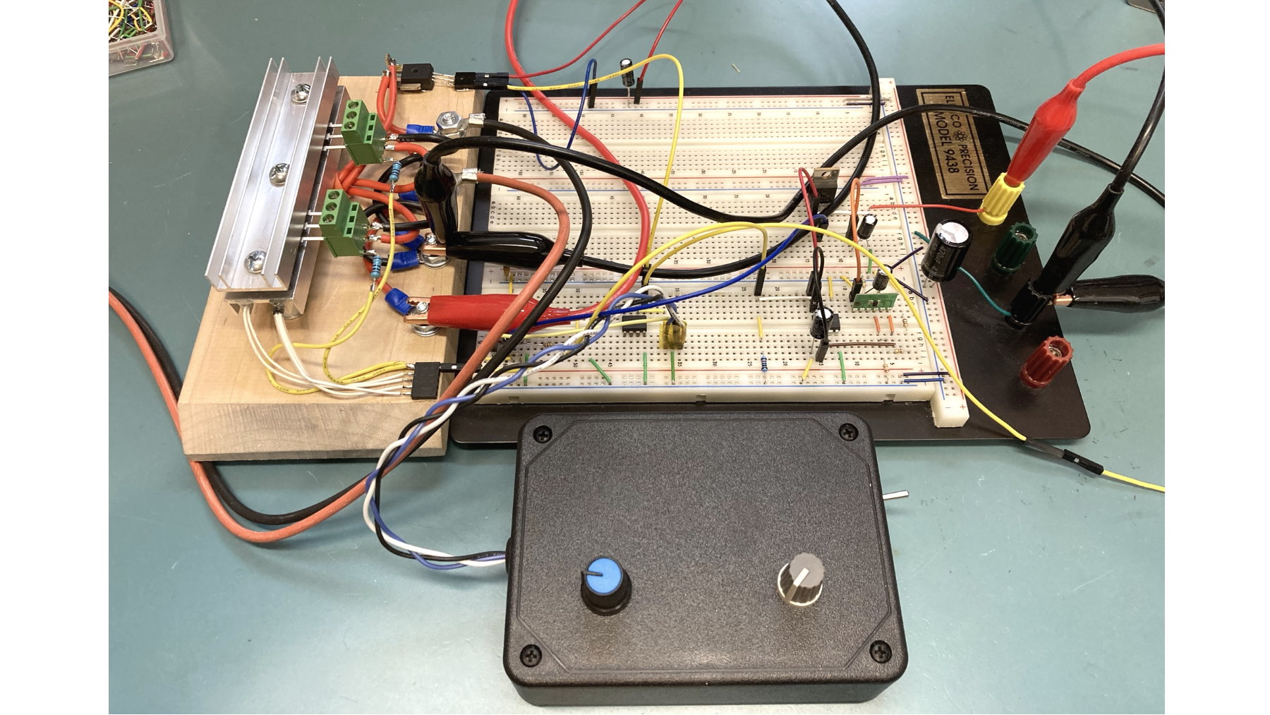
In order to accurately evaluate the performance of parallel MOSFETs or IGBTs, I built a stress testing jig. The jig allows me to place two MOSFETs or IGBTs, in parallel, between two heat sinks and screw them down. The pins of the MOSFETs or IGBTs connect to screw terminals making it easy to swap them out if, or should I say when, I destroy them. The control box has two potentiometers, one for the current limit and one for the throttle. Also, this is my latest and likely final motor controller design with component level current limiting using a voltage controlled oscillator, operational amplifiers and feedback. A future write-up will detail out the design of the motor controller.

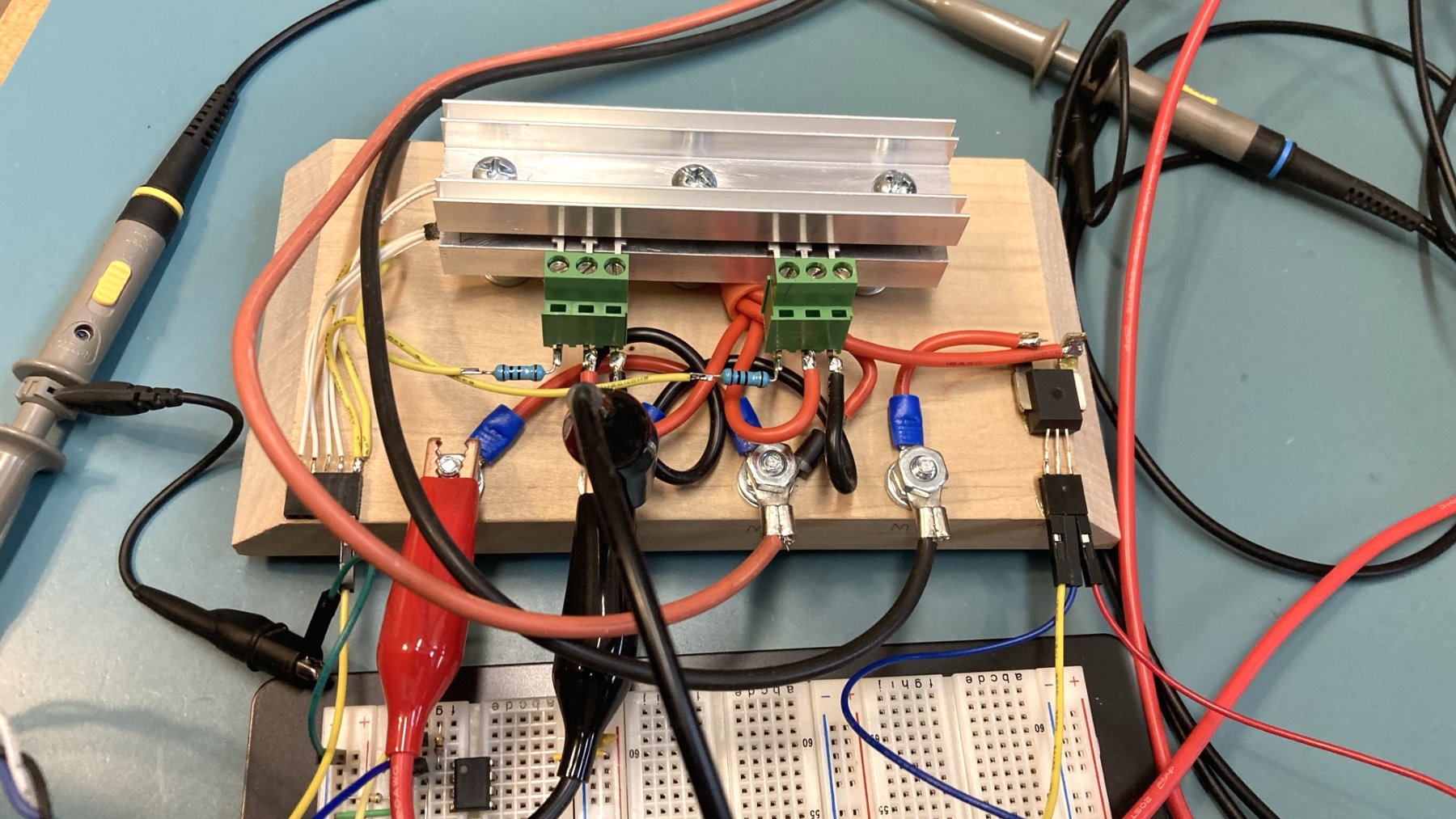
Another shot of the jig. Note the small resistance on the gates to help balance the components. Also note the hall effect current sensor on the right. This communicates with my PIC development board which then displays the current on an LCD display box I designed (next picture).

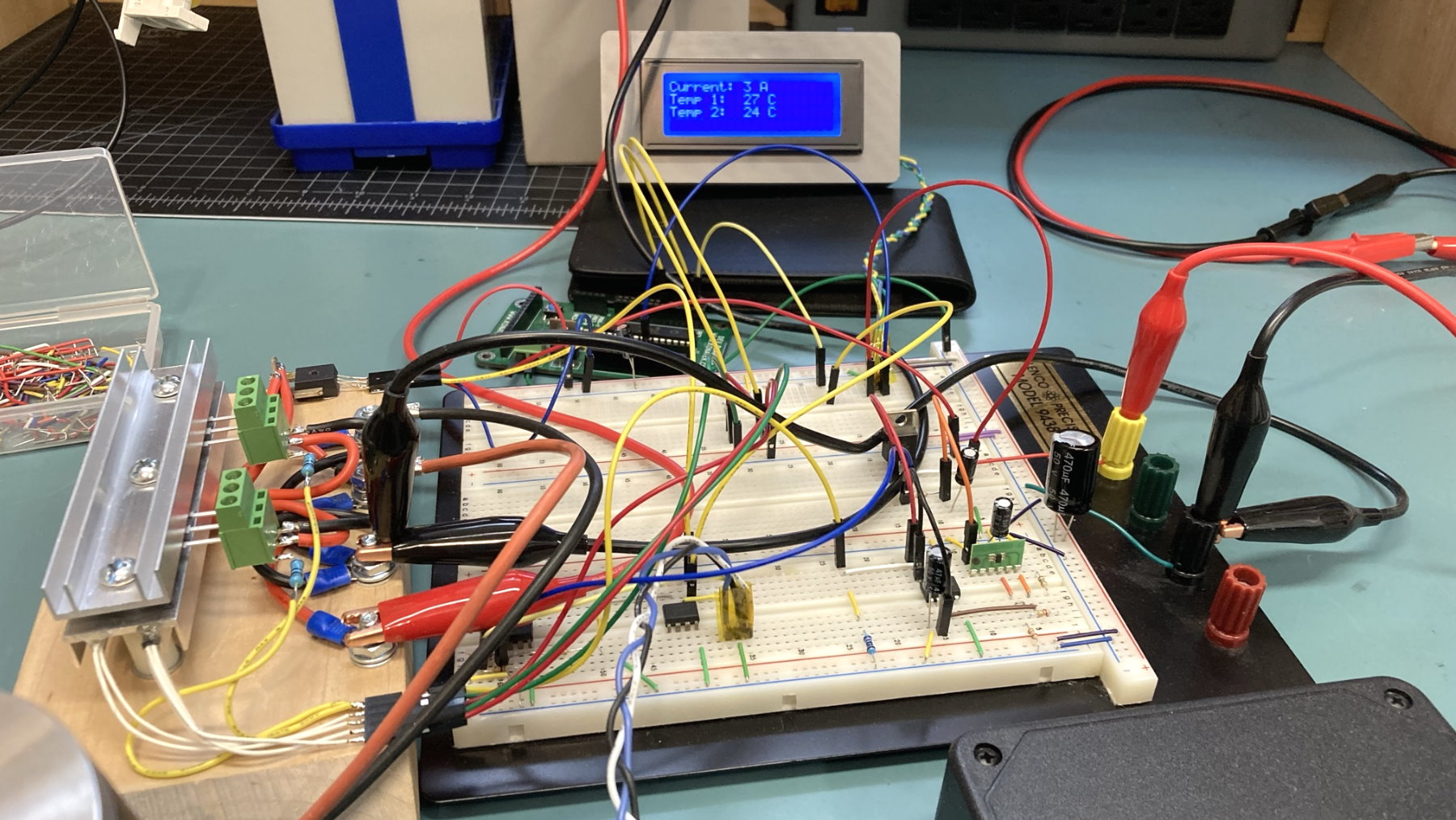
The motor controller is on the breadboard which controls the components under test. The PIC development board reads the signals from the hall effect current sensor as well as the signals from two thermistors which are wired into the heat sinks nearly touching the case of the components under test (see white wires on bottom heat sink). This allows me to monitor the temperature differential between the two components under test as well as the current.
