Motor Controller
by Sidney Kantor
The Vision
After building a small electric vehicle for my son and spending a good chunk of money on a motor controller, I decided to design and build my own motor controller. This was a great learning experience and after building many different versions of an initial design, I will say that I know high voltage/high current brushed DC motor controllers very well. Here are the initial early designs of the motor controller, the progression of the designs and the trials and tribulations along the way.
Bench Prototypes
Early prototype of my first motor controller, a PIC microcontroller using PWM to drive a MOSFET directly. As you can see in later versions, I learned the benefit of using a gate driver to drive the MOSFET. Note the flyback diode across the MOSFET to protect it from the inductive spikes from the motor.
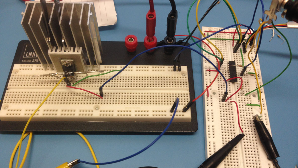
Prototyped motor controller using a PIC microcontroller that uses PWM to drive a gate driver that drives a MOSFET. Also note the Hall effect current sensor. The current sensor works well for limiting the current as long as its below the maximum current the components can handle. The PIC is just not fast enough to read the sensor's voltage via an ADC and then have time to respond. With some software tricks you can improve this design but my next version of this will use hardware current limiting.
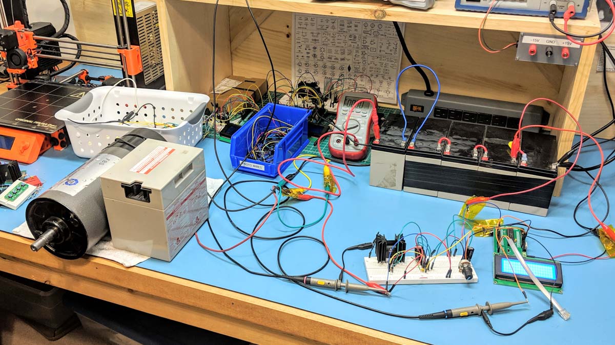
Testing the motor controller prototype with a 130V surplus treadmill motor, 5 12V lead-acid batteries in series making 60V and a 12 V lead-acid battery out of toy electric car to stabilize the motor :-). The LCD was used to display the current which was captured by the Hall effect sensor.
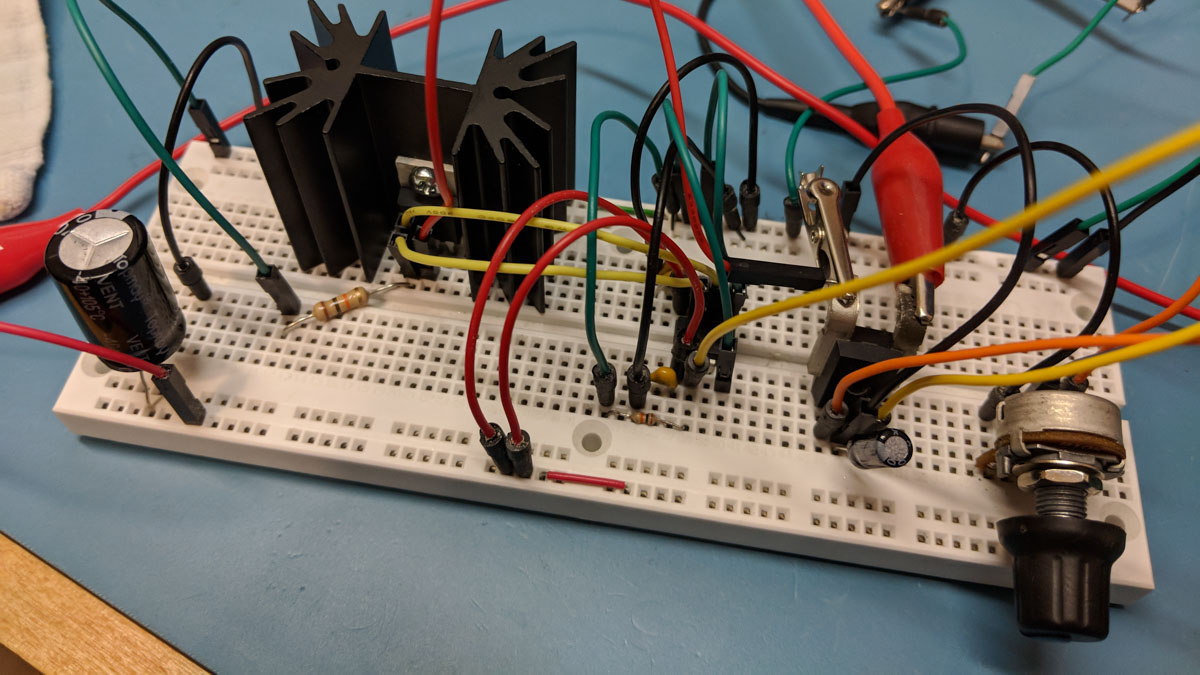
After destroying many lower powered MOSFETs I decided kick things up a notch in terms of the MOSFET power rating and also introduced active cooling to keep the MOSFET junction temperature within its operating range. Here is a power MOSFET mounted to a fan-cooled heat sink salvaged from an old high-end Digital server. These heat sinks were used to cool the server's main CPUs.
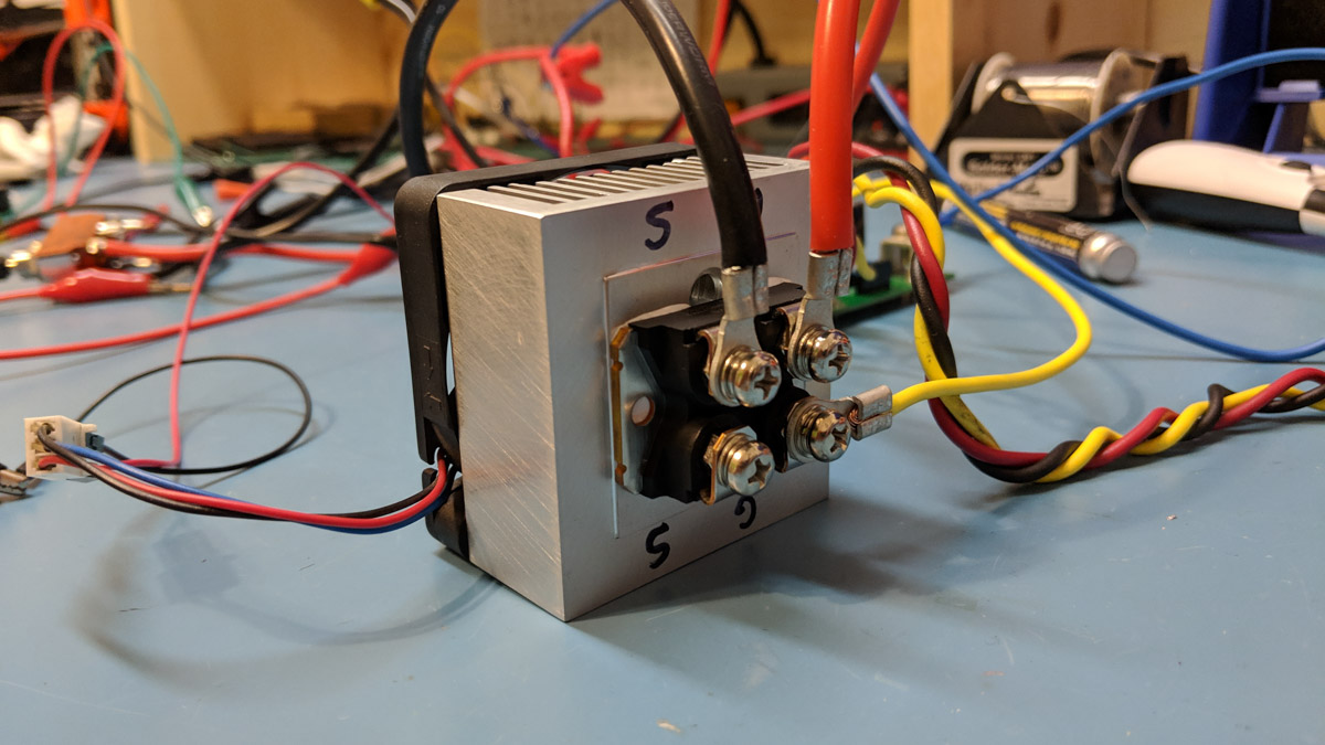
The second version of the high voltage high current motor controller I designed and built which controls a 130V surplus treadmill motor for my son's electric vehicle. I'm currently using a beefy IGBT attached to the fan cooled heat sink. The IGBT is not as efficient as a MOSFET but it's rated at 650V! You can see where I connected the external IGBT wires to the PCB pads where the original, and smaller, MOSFET was mounted.
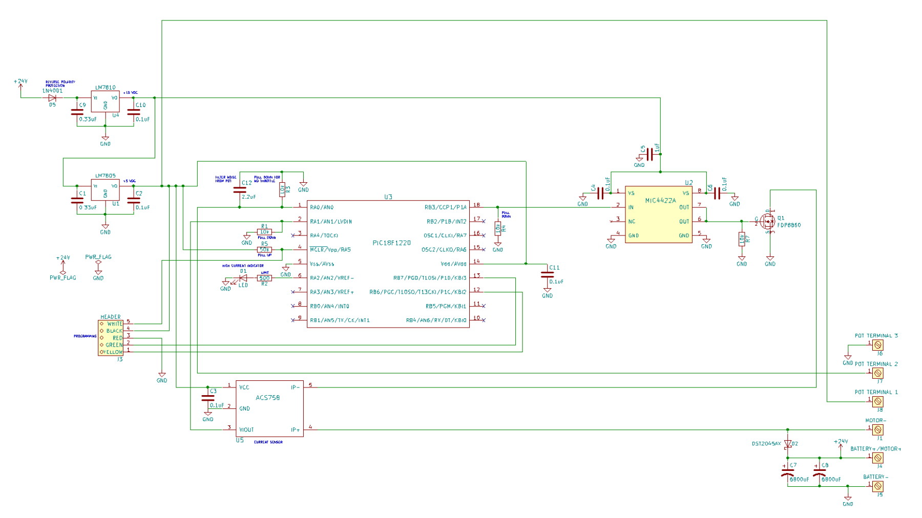
Schematic v1
talk about the design
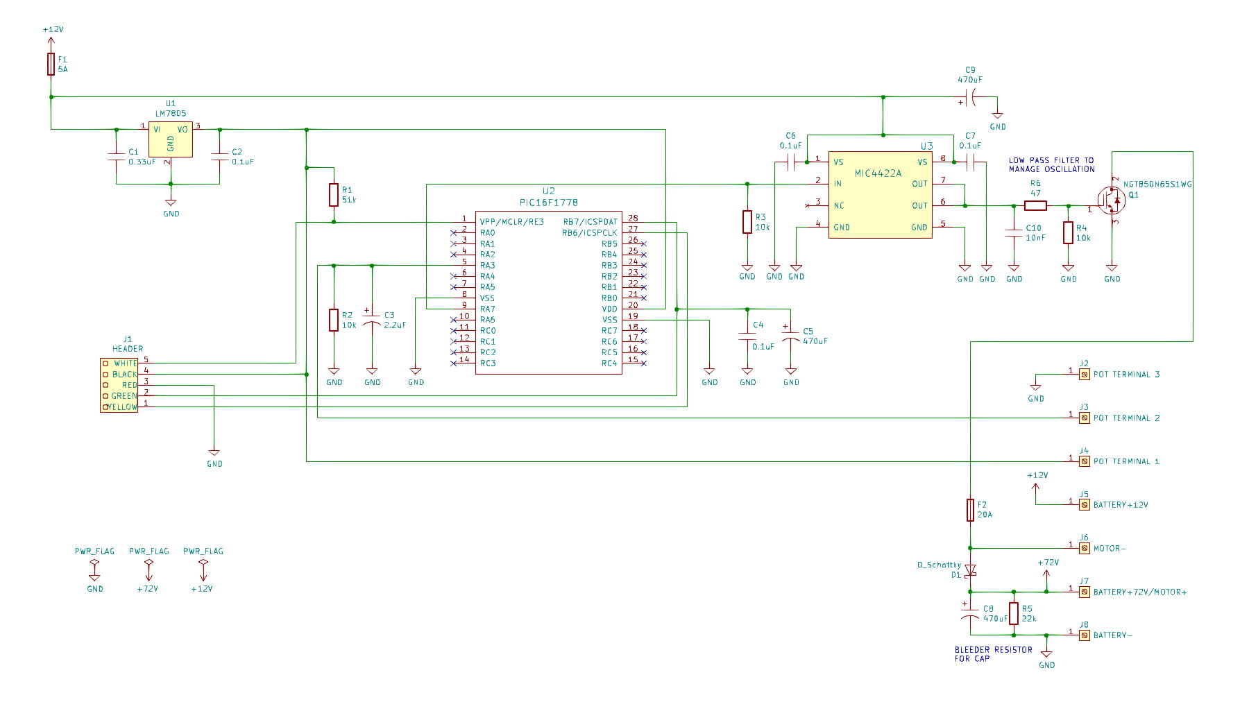
Schematic v2
The second version had some small tweaks including a bleeder resistor for the higher voltage capacitor, use of the PIC16F1778 microcontroller, an RC filter on the gate of the MOSFET to control some rogue oscillation and a higher power MOSFET.
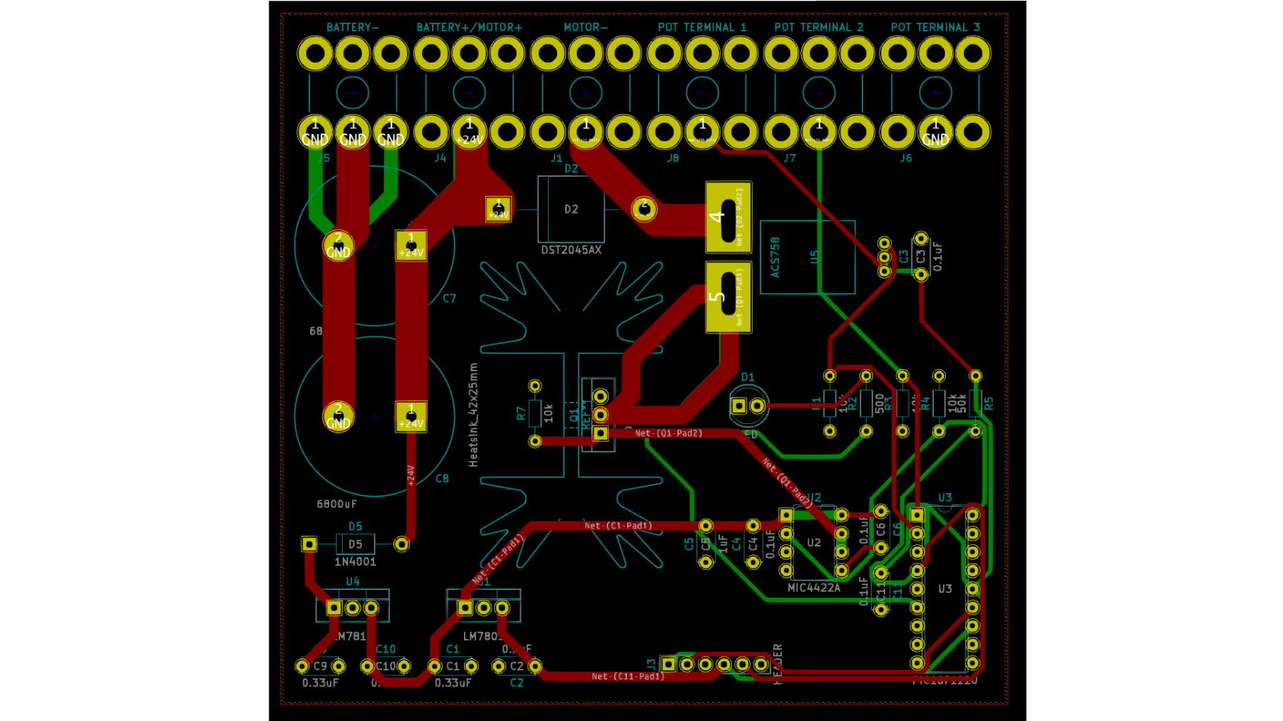
PCB Layout v1
The PCB layout in Kicad. I used very heavy gauge terminal blocks for the battery and motor and potentiometer. I would not do this again. This was definitely overkill and the high thermal conductivity of the terminal blocks made soldering them to the board very difficult. Also, the pontentiometer connects should have been a simple small connector especially given its just a small signal.
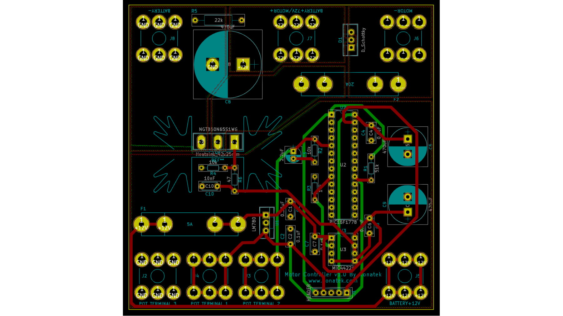
PCB Layout v2
The updated PCB layout in Kicad.
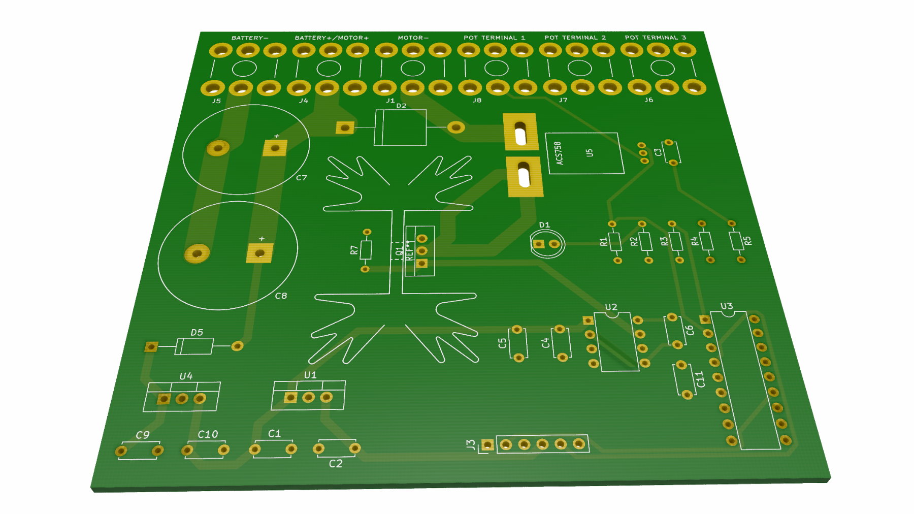
PCB Rendering v1
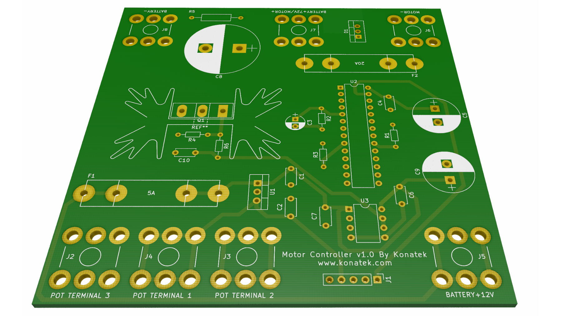
PCB Rendering v2
Manufactured Boards
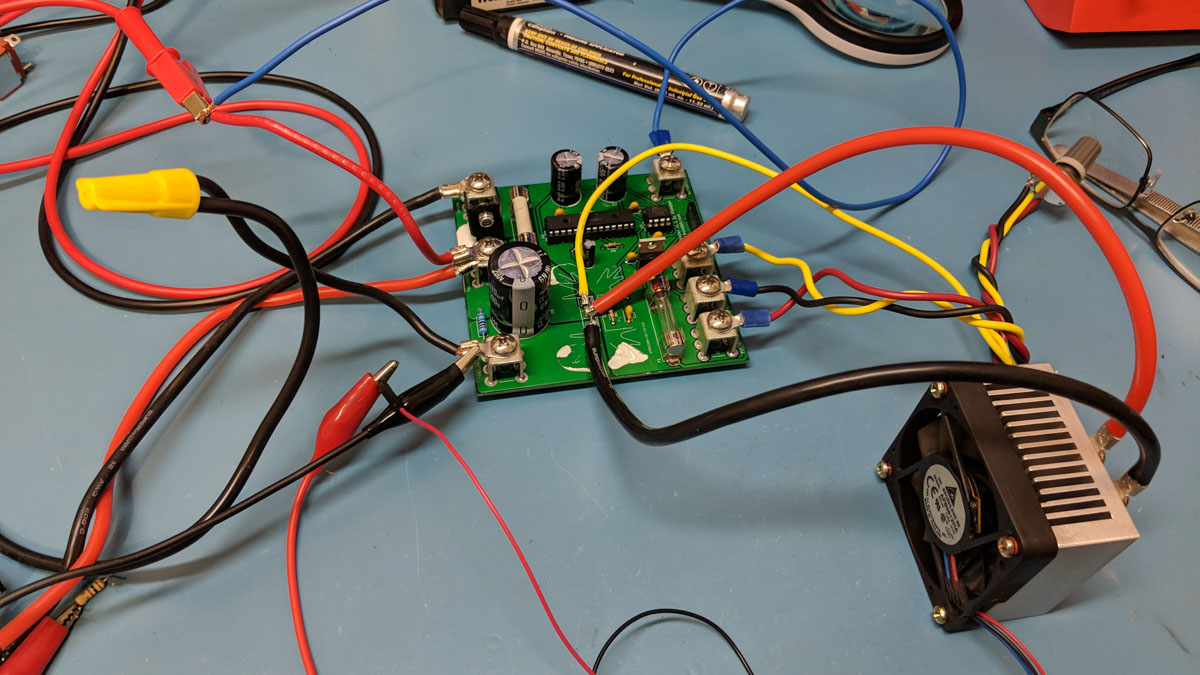
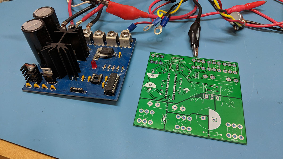
Here is the first version of the motor controller populated and the new unpopulated version (in green).
Going Full Send
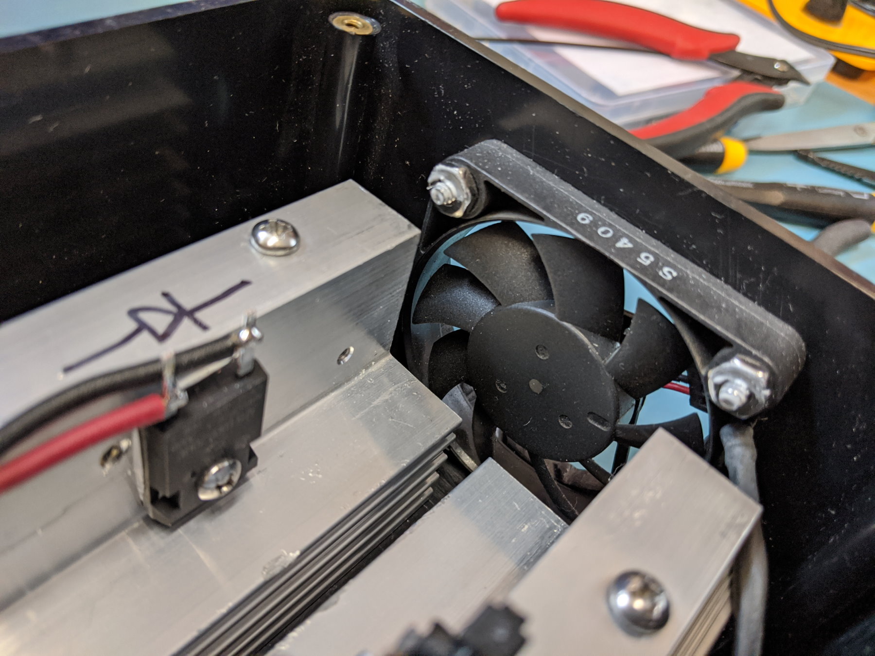
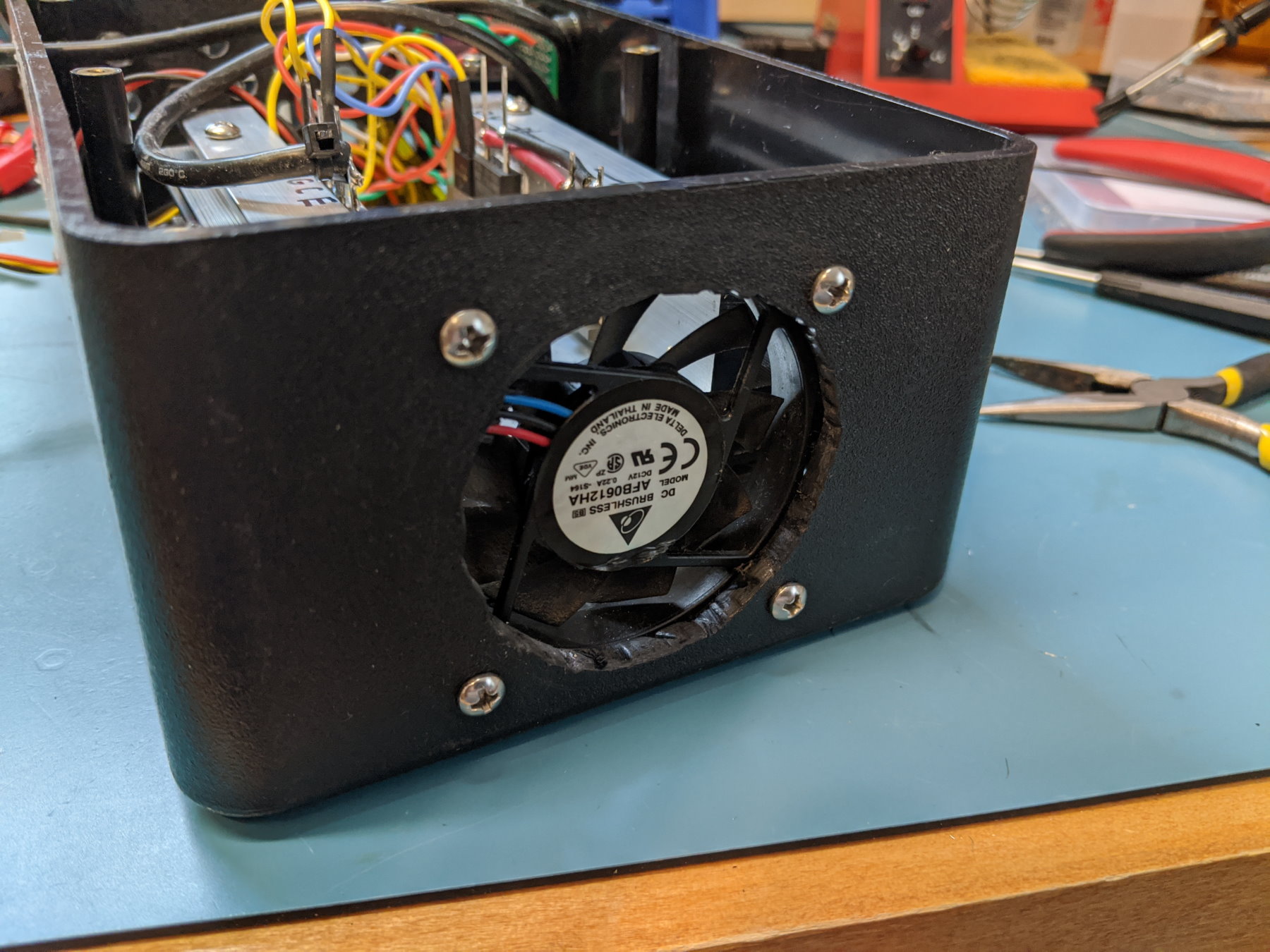
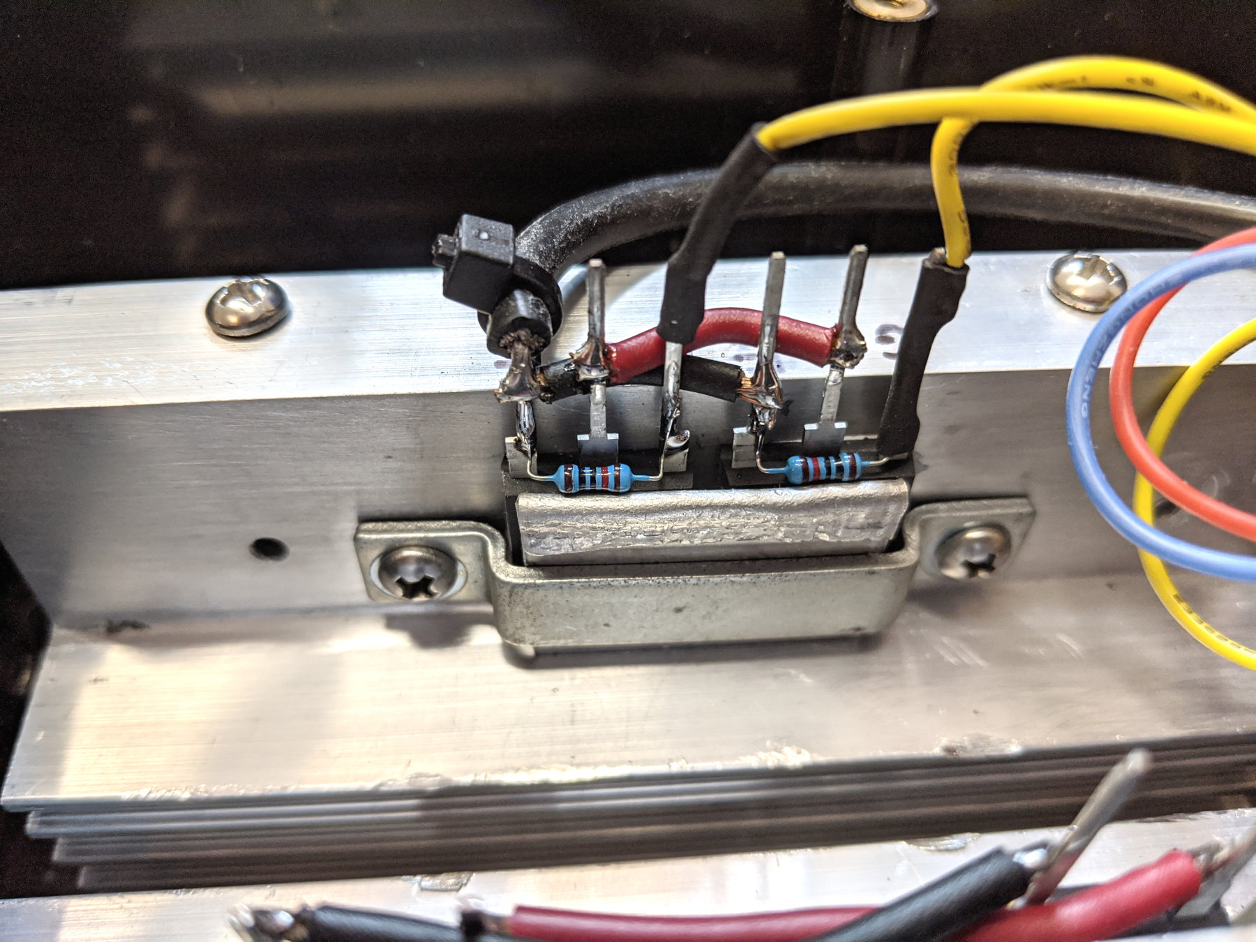
After coming across some monster heat sinks from a salvaged Digital server, I decided to go full send and build a motor controller using one of my PIC development boards, some protoboard, parallel beefy IGBTs and parallel diodes and a large fan cooled enclosure. This motor controller was built using the same principles as my previous motor controllers but is extremely robust given the large thermal mass of the heat sinks along with the active fan cooling. I have abused this motor controller and it has yet to fail me! Enjoy the pictures of this beast slowly coming to life.


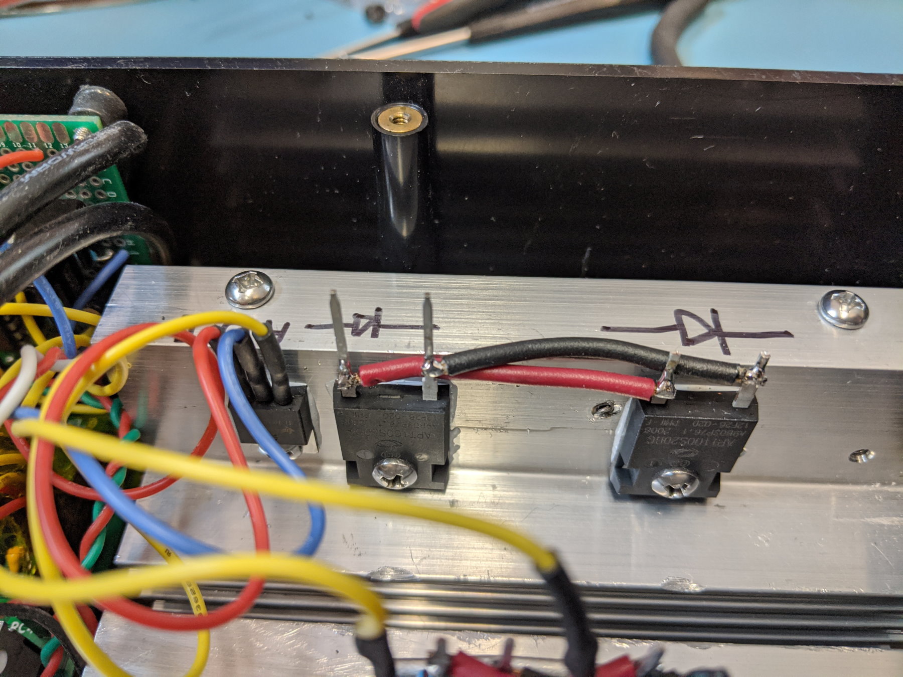
Latest Motor Controller Design
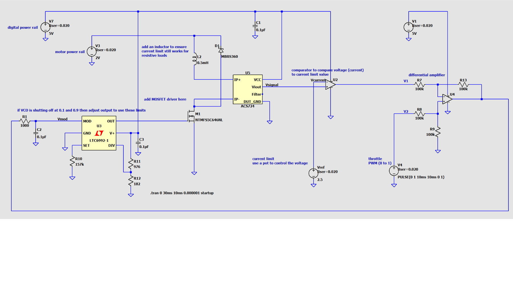
Below is the initial circuit design and simulation in LTSpice for my latest motor controller design which uses a voltage controlled oscillator, opererational amplifiers and feedback to allow for adjustable hardware current limiting. It works very well and I'm looking forward to getting some boards designed when time allows.
